Simple anti corrosion measures.
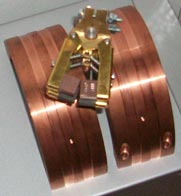
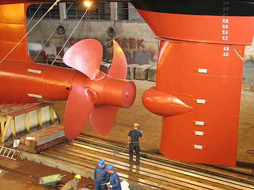
When steel is immersed in sea water (e.g. a ships hull) small galvanic currents are initiated at anodic areas of the metal surface, causing corrosion. Such corrosion predominates at the stern of a ship, where the combined effects of increased turbulence and differential metals results in accelerated corrosion rates. The application of Cathodic Protection effectively suppresses these corrosion cells by applying an opposing current from external anodes and if the propeller is to receive the benefits of cathodic protection then there must be a continuous electrical circuit between the propeller and the ships structure. This circuit usually exists when the propeller is at rest, where a metal to metal contact is made between the shaft and the stern tube liners, or main engine bearings and journals.
However, whilst the shaft is turning the bearing lubrication creates an intermittent high resistance which effectively insulates the propeller from the hull structure and since the propeller presents a relatively large surface area of bare metal, it attracts cathodic protection currents, which tend to discharge by arcing across the lubrication film and in so doing, results in spark erosion which eventually leads to pitting and ‘striping’ of white metal bearing surfaces. It is generally accepted, that the effects of arcing are minimised when the potential across the shaft / hull interface is less than 50 mV.
 bimetallic are leaching higher than recommended levels of Nickel into people that have an acidic sweat, the sweat acts as an electrolyte and promotes the leaching of Nickel into the skin.